pp.49-51
Dinesh Sethi, Scholar, Dept. of ECE,SGVU, Jaipur
Ripu Ranjan Sinha,Dept. of R & D,SGVU, Jaipur
R. K. Khanna,Dept. of R & D,VGU, Jaipur
Abstract—this paper deals with a slot loaded CPW -fed ultrawideband (UWB) printed monopole antenna (PMA) with dual band-notching at W-LAN and X-Band.The antenna is fabricated on an FR-4 epoxy substrate with thickness of 1.6mm and r =4.4. The antenna uses three rectangular slots to create dual band-notched characteristics in 5.15–5.82 GHz for WLAN, and 7.25–8.39 GHz for uplink and downlink of X-band satellite communication systems, respectively. Surface current distributions are used to show the effect of these slots. The proposed antenna has a compact size of 26x30mm2 and operates over 3.15 to 10.63 GHz with VSWR < 2. All simulations in this work have been carried out by using the electromagnetic software Ansoft HFSS 13. Details of the proposed antenna are presented along with measured and simulated results.
Keywords—CPW antenna, UWB antenna, band notch antenna, planar monopole antenna.
I. INTRODUCTION
WIRELESS communication has become a necessity for a long time due to cost effective characteristics and received great attention by the peoples from academics and industries when federal communication commission (FCC) declared unlicensed radio frequency band 3.1-10.6 GHz for commercial use [1]. In recent years researchers have improve the various challenges of UWB antennas like, impedance bandwidth, radiation patterns, matching characteristics and compact size of the antenna. UWB has attractive merits such as small size, low cost, ease of fabrication, high data rate, wide impedance bandwidth and good omnidirectional radiation [2]. UWB systems have disadvantage that they are very sensitive to electromagnetic interferences with existing narrowband wireless communication systems, so it is necessary to design antennas with multiband filtering characteristics to avoid interferences. UWB (3.1 GHz to 10.6 GHz) includes sub narrowband applications like WiMAX operating in 3.3-3.6 GHz band, C band (3.8-4.2 GHz), WLAN (5.15-5.82) GHz band and X band satellite communication system operating in 7.25-8.39 GHz band. These bands could be rejected with bandstop filters in UWB, but this approach will increase the complexity of the system. Therefore it is necessary to design the UWB antenna with band notched characteristic to reduce the complexity and make cost effective systems. In past different methods have been proposed and presented to design UWB with band notch characteristics, these included different type of slots on the radiating patch or on the ground plane, split-ring resonators, tuning stubs, meandering, folded strips, EBG structure etching on patch/ground plane [3-15].For example, etching of U slot [3-4], V- shaped slot [5], Cshaped slot [6], S- shaped slot in feed line[7], a quasi complementary split ring resonator (CSRR) in fed line [8], a quarter- wavelength tuning stub in a large slot on the patch [9], or compact folded stepped impedance resonators (SIRs) or capacitively loaded loop (CCL) resonators in fed [10-11], a parasitic slit along with tuning stub used [12], C shaped slot on patch and L shaped stub on ground [13], semi-circular slot on patch [14]. In this paper, we have proposed a compact CPW fed UWB planar monopole antenna with dual notched bands for 5.15-5.82 GHz band (WLAN) and 7.25-8.39 GHz band (X-band satellite communication) using quarter wavelength slots on patch. The complete antenna size is 26×30 mm2 . The proposed antenna has notch at X- band satellite communication bandfrom 7.25-8.39 GHz which include uplink and downlink band whereas antenna proposed [8],[14],[15] were covers only downlink band of X – band satellite communication.
II. ANTENNA DESIGN AND ANALYSIS
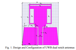
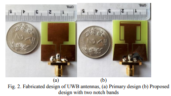
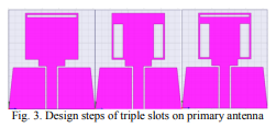
The geometry and configuration of the proposed antenna optimized with the Ansoft HFSS 13is shown in Fig. 1. This antenna is printed on the FR 4 substrate with thickness of 1.6 mm, dielectric constant of r =4.4, and loss tangent of 0.02. A CPW feeding with width of the microstrip feed line 3.00 mm have been used to achieve 50-Ω characteristic impedance. With edge taperedground, three rectangular slots have been cut on radiating patch namely S1, S2& S3usedto achieve dual notch at WLAN and X band respectively. Slots S2& S3 are symmetrical and it provides the notch at X band satellite communication.A rectangular slot S1 was cut on the radiating patch with SL1 = 0.75 mm and Sw1 =15 mm, which is about a quarter of the wavelength (λ/4) calculated at 5 GHz in the WLAN band. Slot S1 provides notch of 5.18-5.82 GHz for WLANs applications. Slots S2& S3 have the equal dimension, width Sw2 =Sw3= 2.85 mm, and length SL2 = SL3 = 10.25 mm, that is approximately quarter of wavelength (λ=c/f) calculated at 7.25 GHz in X–band satellite communication band. The optimized dimension of the proposed antenna has been presented in table 1. Fabricated design of primary and proposed antenna has been presented in Fig. 2. (a) & (b), respectively.
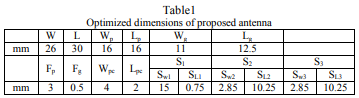
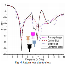
The return loss (S11 in dB) and VSWR due to the slots S1, S2& S3 have been presented by Fig.4 and Fig. 5 respectively. From Fig. 4 and Fig. 5, we can see that slot S1 provides a single band notch characteristic in UWB band. Now to achieve the notch at higher frequency we have used two slots S2& S3 cut on primary antenna. From Fig. 4 and Fig. 5 it can be seen that slots S2& S3 provides a single notch at frequency band 7.25- 8.39 GHz. Now to achieve the dual notch band in UWB for WLAN band and X band satellite communication system, we have combined all three slots namely S1, S2& S3 on radiating
patch, it provides dual band notch characteristic in UWB range for WLAN and X band satellite communication systems. The returnloss of combined slots on radiating patch have been presented in Fig.4. All three steps have been presented in Fig. 3.
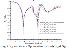
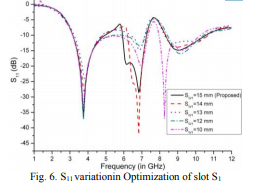
Length of slots namelySw1, SL2 and SL3 were varied with a range of values and results are presented. From Fig.5, it can be seen that with the length of SL2 & SL3 at 11 mm, 10.75 mm, 10.50 mm we were not able to achieve our desired notch band and with 10 mm it is very near to the desired band but we have achieved desired notched band with the proposed length of 10.25 mm. The width optimization of slot S1 and its effect on the S11 has been shown in Fig. 6.
III. RESULT AND DISCUSSION
The measurement of proposed antenna was performed with network analyzer for return loss & VSWR and anechoic chamber for Ludwig 3rd radiation pattern. Measured result shows good agreement with the simulated result. A simulated and measured return loss result of proposed antenna has been shown in Fig.8.The antenna with three quarter wavelength slots successfully exhibits dual notched bands of 5.18 – 5.82 GHz and 7.25 – 8.39 GHz, maintaining broadband performance from 3.1 to 10.6 GHz (UWB frequency band) with VSWR less than 2.
IV. CONCLUSION
A compact dual band notched UWB antenna with measured results has been presented in this paper. This antenna has simple structure and compact size of 26 x 30 mm 2 , which is easy to be implanted in miniature devices. Proposed antenna covers frequency band from 3.1 to 10.6 GHz, where simulated and measured results are good in agreement. To prevent interferences with WLAN and X band satellite communication systems, two band rejection structures are selected to produce sharp rejection. Result & analysis of this antenna indicates that it is applicable in miniature devices, simple design and compact size as added advantage.
REFERENCES
[1] First report and order, Revision of part 15 of the commission’srule regarding ultra-wideband transmission system FCC 02-48, Federal Communications Commission, 2002.
[2] Z. N. Chen, “UWB antennas: From hype, promise to reality,” in IEEE Antennas Propag. Conf., 2007, pp. 19–22.
[3] W.-S. Lee, K.-J. Kim, D.-Z. Kim, and J.-W. Yu, “Compact frequency notched wideband planar monopole antenna with an Lshaped ground plane,” Microw. Opt. Technol. Lett., vol. 46, no. 4, pp. 340–343, 2005.
[4] F. Fan, Z. Yan, T. Zhang, and Y. Song, “Ultra-wideband planar monopole antenna with dual stopbands,” Microw. Opt. Technol. Lett., vol. 52, no. 1, pp. 138–141, 2010.
[5] Y. Kim and D.-H. Kwon, “CPW-fed planar ultra wide band antenna having a frequency band notch functions,” Electron. Lett., vol. 40, no.7, pp. 403–404, 2004.
[6] Q.-X. Chu and Y.-Y. Yang, “A compact ultrawideband antenna with 3.4/5.5 GHz dual band-notched characteristics,” IEEE Trans. Antennas Propag., vol. 56, no. 12, pp. 3637–3644, Dec. 2008.
[7] S.-W.Qu, J.-L. Li, and Q. Xue, “Aband-notched ultrawideband printed monopole antenna,” IEEE Antennas Wireless Propag. Lett., vol. 5, pp. 495–498, 2006.
[8] W. T. Li,X.W. Shi, and Y. Q. Hei, “Novel planar UWB monopole antenna with triple band-notched characteristics,” IEEE Antennas Wireless Propag. Lett., vol. 8, pp. 1094–1098, 2009.
[9] K. S. Ryu and A. A. Kishk, “UWB antenna with single or dual band notches for lower WLAN band and upper WLAN band,”IEEE Trans. Antennas and Propag., vol. 57, no. 12, pp. 3942–3950, Dec. 2009.
[10] Y. Sung, “UWB monopole antenna with two notched bands based on the folded stepped impedance resonator,” IEEE Antennas Wireless Propag. Lett., vol. 11, pp. 500–502, 2012.
[11] C.-C. Lin, P. Jin, and R. W. Ziolkowski, “Single, dual and triband-notched ultra-wideband (UWB) antennas using capacitively loaded loop (CLL) resonators,” IEEE Trans. Antennas Propag., vol. 60, no. 1, pp. 102–109, Jan. 2012.
[12] Rezaul A., M.T. Islam, and A.T. Mobashsher “Design of a Dual band notch UWB slot antenna by means of simple parasitic slits,” IEEE Antennas Wireless Propag. Lett., vol. 12, pp. 1412–1415, 2013.
[13] Peng Gao, L.X., J.Dai, S.He and Y.Zheng, “Compact Printed wide slot UWB antenna with 3.4/5.5 GHz dual band-notched characteristics,” IEEE Antennas Wireless Propag. Lett., vol. 12,
[14] pp. 983–9
[15] 86, 2013.