| Chanchal Sharma 1, Dr Mukesh Kumar Gupta2, Sandhya Sharma3
Ph.D. Scholar 1, Associate Professor 2 Associate Professor3 engineer.sharma23@gmail.com 1mkgupta@gmail.com2 Suresh Gyan Vihar University, Mahal,Jagatpura,Jaipur1,2,3 |
Abstract—The FCC declare 7.5 GHz from 3.1 to 10 GHz for UWB applications , UWB is high data rate communication technology and the micro strip patch antenna giving bandwidth enhancing 1 to 5%. This Bandwidth is increasing techniques is important areas of research in the field of micro strip antenna table s. The BW is percentage of width is acerbically the bandwidth is defined as a percentage of width of the range of acceptable frequencies and the resonant frequencies of the antenna. The. parameter such as radiation efficiency return loss and voltage standing wave ratio (VSWR) are often used to define the bandwidth of a micro strip antenna. To choose an optimum antenna for ultra-wide band several factor will effective The main challenge in UWB antenna design is achieving every broadband width with high radiation efficiency and small size. Many techniques the impedance bandwidth of small antennas and to optimize the characteristics of broadband antennas have been widely investigated and in various published papers as listed in this survey paper
Keywords: Bandwidth, Efficiency, Micro strip antenna, Wide Band
INTRODUCTION
Ultrawideband(UWB) technology has been regard ecdysone of them of promising wireless technologist peaceability of revolutionizing high data rate transmission. Since the FCC release 7.5 GHz bandwidth (3.1- 10.6 GHz) for UWB wireless communication, Many new techniques to support high data rate wireless communication have been rapidly developing. Primary barrier to implement patch antenna in modern broadband communication system application is its narrow bandwidth. The micro strip antennas are often
realized with band width of the order of 1%to5% .Bandwidth enhancement technique is one of the areas of researchinthefieldofmicrostripantennas.Theparameterssuchasradiationefficiency,return loss, and voltage standing wave ratio (VSWR) are often used to define the bandwidth of a micro strip antenna. In order to fulfils the UWB antenna for planar monopole antennas have been develop during last decades.In this paper various techniques of the recent trends like antenna designing with (a ) modified ground plane (b) slot truncation and notches cutting (c) by adding two parasitic elements on novel microstrip antenna (d) hybrid dielectric resonator antenna (e)composite cavity-backed folded sectorial bowtie antenna for improving the impedance bandwidth of small antennas reported in the literature are discussed.
I. Method of Bandwidth Enhancement Technique
A. A Modified Ground Plane UWB antenna
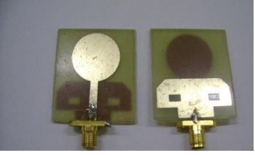
In this article the authors report at technique to enhance the bandwidth using a microstrip–fed planar circular disc monopole [3].The circular disc monopole with a 50 Ω micro strip feed line is fabricated on the FR4 substrate. To improve the bandwidth they modified the original Final Stage original ground plane to be T shaped with diagonal cuts at the top corners and rectangular slots on the body .
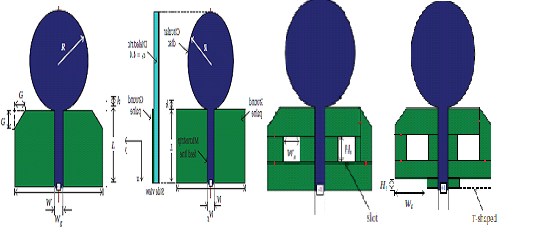
(a)Original shape (b)With diagonal edges
(c)with slot(d) with T shaped cut on ground plane
Fig.1: Geometries of the circular microstrip antennas
Fig. 2: Fabricated Proposed Antenna
In this paper a compact antenna and a technique to increase its bandwidth have been proposed and implemented .and result shows that the bandwidth mainly depends on the circular disc size and the make it parameters ,the proposed antenna can be tuned and the ground plane. With the presence of the diagonal cut are as at the corner so the ground plane ,the band width can be further improve and the size of the ground plane has significant impact on the performance can b reduced to satisfy a compact size design. Bandwidth Enhancement by Use of Slots Truncation and Cutting Notches: In this system consistent with authors the geometry of antenna originates from convention rectangular monopole and is realized by adding T slot for both patch and feeding strip[10].. The T slot cutting on patch and feeding strip has disturbed the present direction thus provide a broad bandwidth. This is thanks to the geometry of an antenna implies the present courses as shown in fig 2 and Fig. 3: Photograph of Slotted Antenna This paper declare that return loss performance f antenna without wo notches at the bottom start degrading its performance at7.5 GHz. this is thanks to more horizontal current mode occurs within the whole structure which degrade the polarization properties the impedance bandwidth performance of the antenna[13-16] . In order to modify the equivalent characteristics impedance on the antenna, which is location the centre of smith chart Around matching impedance. which is found at the centre of smith chart .it also shows that the one step and three steps notches cutting at rock bottom give more capacitive to the antenna than the two steps notches especially at higher frequency ranges. The ground plane as an impedance matching circuit and also it tunes the resonant frequencies result shows that the present density
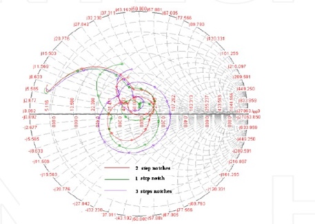
Fig.4:simulated and measured impedance result
by increasing the frequency. most vertical electrical current is distribution near to T slot edges rather than distribution on the antenna surface. To validated the simulation results an antenna prototype was fabricated and tested. That is inductance.[18]
The resonance frequencies are shifted from the simulated result but they are still covering the UWB bandwidth
requirement. The return loss curves of frequency ranges above 10.5 GHz are getting, worst. In addition, since the antenna is fed by micro strip line, misalignment can result because etching is required on both sides of the dielectric substrate. The alignment error results degradation to the antenna performance. In this paper bandwidth enhancement techniques have been presented. The T slotted antenna has been designed and developed. Three bandwidth enhancement techniques were adopted in order to produce a small sloted UWB antenna. This proposed antenna uses two notches, T slot and a partial ground plane, An experimental prototype has been fabricated and tested. It shows that the measured return loss covering the UWB bandwidth requirements of 3.1 to 10.6 GHz with respect -10dB.The measured radiation pattern of this prototype are also presented at frequencies 4,5,8 and 10.6 GHz respectively
B. Bandwidth Enhancement by Adding Two Parasitic Elements on Novel Micro Strip Antenna
In this paper authors presented a noval microstrip antenna with wide band width, two different radiating elements connected together through a matched section and are embedded on a single layer structure . That new technique offers a dual bandmicro stripantennabycontrollingthetwo resonance frequencies of the two elements ,a wide frequency bandwidth approximately 9% has been achieved. A more bandwidth enhancement upto 12% has been achieved by adding two parasitic
Elements to one element of that proposed antenna another way to improve the bandwidth of an MPA is to create several resonant structure in to one antenna by adding more layers more patches or more extra component[21-24] . Single layer double band antenna will be achieved from below mentioned techniques that the reactively loaded microstrip antenna[25]where two different coaxial stub are use another one is the dual band microstrip antenna with monolithic reactive loading[26]or with modified circular disc by adding additional strip[27], or by patch trimming with a rectangular notch[28], or by adding shorting pin [29] These concepts are ideal for closely main goal of that presented article was to present a new antenna configuration with dual band offering dual band frequency with a controllable of frequency ratio of the two elements.
Fig. 5: (a) Configuration ofdual band MPA
That new technique offers a dual band micro strip antenna by controlling the whose resonance frequencies of the two elements, a wide frequency bandwidth of approximately 9% has been achieved. A more bandwidth enhancement upto12%has been achieve by adding two parasitic element stone element of that propose antenna another way to improve the band width of an MP Aristo creates ever alresonants tructure into one antenna by adding more layers more patches or more extra component[21-24] . Single layer double band antenna will be achieved from below mentioned techniques that are there actively loaded microstrip antenna[25]where two different coaxial stubs are use another one is the dual band microstrip antenna with monolithic reactive loading[26]or with modified circular disc by adding additional strip[27], or by patch trimming with a rectangular notch[28], or by adding shorting pin [29] These concepts are ideal for closely space brand shaving frequency ratio upto1.5:1.The other techniques for multiband antennas is multiple layers which consisting of two or more metallic patches supported by one or more dielectric layers The main goal of that presented article was to present a new antenna configuration with dual band offering dual band frequency with a controllable of frequency ratio of the two elements.[30-33] Fig. 5: (a) Configuration of dual band MPA Fig: 5. (b) Configuration of the wide band MPA with parasitic elements They got a wide bandwidth antenna configuration by overlapping the two element frequency response and the frequency response of the dual element was controlled and the performance of antenna was improve by using two parasitic elements with The investigated wide bandwidth antenna is a good candidate for many wireless communications[35]UWB Hybrid Dielectric Resonator Antenna :In this paper a novel hybrid dielectric resonator (DR)antenna for ultrawideband(UWB) short range wireless communications is proposed. The proposed antenna consists of a micro strip fed monopole loaded with a half cylindrical dielectric resonator antenna of Rogers RO301 mounted on RT5880 substrate with a granite ground plane[36-37].The microstrip line fed monopole antenna is not other side of the substrate .Compare to the conventional circular cylindrical DR mounted on a granite ground plane. The proposed antenna was a good impedance bandwidth. More ever, the antenna has a good Omni directional radiation pattern in the H plane. The proposed antenna was considered a good candidate for UWB short range wireless communication systems[38-40]. Fig. 6: (a) Evolution of proposed antenna Step 1: Size Reduction Fig. 6: (b) Evolution of proposed antenna step 2:
Bandwidth Enhancement The propose antenna had size enhancement about 30%t and the antenna in figure 5(a) with a reduction in then operating band width by 8% . Figure 5 (b) presents the antenna impedance bandwidth enhancement by loading the monopole antenna having as lot in the truncated ground plane of the microstrip substrate of width with dielectric resonate or antenna. It is clear that he proposed antenna works as a monopole antenna loaded by a half cylindrical DRA. . Adding the DRA to the monopole antenna excites new resonances especially at low frequency band.[41]UWB Composite Cavity-Backed Folded Sectorial Bowtie Antenna: In this technique suavity Backed structure are employed construct a UWB antenna with unidirectional pattern ,because they have relatively low profiles, wideband characteristics , high efficiency to a cup shape one as showninFigure6.Parametric studies are performed to optimize the antenna performance. and experimental results revealed SWR less than equal to 2 and 143% bandwidth enhancement [42] They can be taken as a combination of two radiators the exciter and the rim of the cavity [43-44], and their aperture efficiency can reach over 100% in some frequency bands , especially at lower frequencies, because the electric fields are extended far away from their physical apertures. The selection of the exciter for this type of antenna is critical as the operating bandwidth of the exciter determines that of the final design. Fig. 7: Geometries of the proposed composite cavity backed FSBA (a) 3D view (b) Side view In this technique a dual folded sectorial bowtie antenna (FSBA)is employed as the exciter and it shows many advantages over the ordinary sectorial bowtie antenna (SBA), such as flatter input impedance smaller electrical dimensions and gain fluctuation . and a composite cavity , consisting of a conical part and a cylindrical rim, is used to optimize the electric field distributions in the aperture or the stable radiation patterns.[45]This composite cavity is firstly used in short back fire antennas. But they only achieved a narrow operating bandwidth of 20% and electrical dimension as large as in diameter and as in height ,due to the leaky wave structure of the short backfire antenna. A wide band composite cavity backed FSBA is investigated in this paper . The difficulty encountered by the disk or cavity backed UWB antenna in stabilizing the radiation pattern over a large frequency band overcome in this paper by properly choosing the cavity shape and exciter. Parametric studies are performed leading to the practical design. Measurements reveal that the designed antenna features an impedance bandwidth of 143%, a gain of 8-15.3 dB and stable radiation patterns The overall dimension of the proposed antenna are in diameter and in height I.
CONCLUSIONS AND FUTURE WORK
A detailed literature survey has been carried out and various techniques of enhancement bandwidth antenna are presented in this paper. Antennas based on these techniques are also discussed. It has been shown that in micro strip antenna for ultra-wide band has limited bandwidth so using above mention techniques can improve its bandwidth .as desired level The future work includes selection of a specific antenna design use of software for simulations the prototype will be built tested and measure to verify the performance and parameter requirement and aim to get band width enhancement with suitable technique.
REFERENCES
- G Prokis, Digital communications, Mcgraw- Hill , New York, NY, USA1989
- E.Shannon, “A mathematical theory of communication, “The Bell system Technical Journal, vol. 27, pp.379-423,623-656,1948.
- Liang,C.C.Chiau, X. Chen, and C.G Parini,”Study of a printed circular dic monopole antenna for UWB system, “IEEE Transactions on Antennas and Propagation, Vol.53, ,.
- K. Sharma and A. Mittal, “Diagonal slotted diamond shaped dual circularly polarized microstrip patch antenna with dumbbell aperture coupling,” in Proceedings of the 8thEuropean Conference on Wireless Technology, pp. 463–465,2005.
- A. Alkanhal and A. F. Sheta, “A novel dual-band reconfigurable square-ring microstrip antenna,” Progress in Electromagnetics Research, vol. 70, pp. 337–349,2007.
- G.Kharakhili,M.Fardis,G.Dadashzadeh,A.Ahmadi, andN.Hojjat,“CircularslotwithanovelcircularmicrostripopenendedmicrostripfeedforUWB applications,” Progress in Electromagnetics Research, vol. 68, pp. 161–167,2007.
- Song, Y.-C. Jiao, G. Zhao, and F.-S. Zhang, “Multiband CPW-FED triangle-shaped monopole antenna for wireless applications,” Progress in Electromagnetics Research, vol. 70, pp.329–336,2007.
- Sadat, M. Houshmand, and M. Roshandel, “Design of a microstrip square-ring slot antenna filled by an H-shape slot for UWB applications,” Progress in Electromagnetics Research, vol. 70, pp. 191–198,2007.
- -J. Jiao, G. Zhao, F.-S. Zhang, H.-W. Yuan, and Y.-C. Jiao,“A broadband CPW-FED T-shape slot antenna,” Progress in Electromagnetics Research, vol. 76, pp. 237–242,2007.
- Zaker, Ch. Ghobadi, and J. Nourinia, “A modifiedmicrostrip-fed two-step tapered monopole antenna forUWB and WLAN applications,” Progress in Electromagnetics Research, vol. 77, pp. 137–148,2007.
- Eldek,(2006).Numericalanalysisofasmallultrawidebandmicrostrip-fedtapmonopoleantenna.ProgressInElectromagneticResearch,PIER65,pp.59- 69 [13]
- Roblin et al., (2004). Antenna design, analysis and numerical modeling for impulse UWB.International Symposium on Wireless Personal Multimedia Communication (WPMC) 2004 (Ultrawaves invited communication). Abano Terme, Italy. Sept. 12–15,2004.
- Valderasetal.,(2006).DesignofUWBfolded platemonopoleantennasbasedonTLM.IEEETransactionsonAntennasandPropagation,Vol.54,No.6, pp. 1676-1687,June2006.
- Gueguenetal.,(2005).AlowcostUWBprinteddipoleantennawithhighperformance.IEEEInternationalConferenceonUltraWideband(ICU),Zurich, 5-8th Sept,2005.
- Compact wide-band planar monopole antenna. Electronics Letters, Vol.35, No. 25, pp. 2157-2158, December1999.
- Ghannoum et al., (2006). Small-size UWB planar antenna and its behavior in WBAN/WPAN applications. IET seminar on Ultra wideband System, Technologies and Applications, April2006.
- Marta Cabedo Fabres(a) et al.,(2005). On the influence of the shape of planar monopole antennas in the impedance bandwidth performance. International Union of RadioScience(URSI).
- Marta Cabedo Fabres(b) et al., (2005). “On the influence of the shape of planar monopole antennas in the impedance bandwidth performance, “Microwave and Optical Technology Letters, Vol. 44, No. 3, Feb
- J. Ammann and Z. N. Chen, (2004). An asymmetrical feed arrangement for improved impedance bandwidth of planar monopole antennas. Microwave Optical Technology Letters, Vol. 40, No. 2, pp.156-158
- James, J. R. and P. S. Hall, Handbook of Microstrip Antennas,Peter Peregronic Ltd., London,1989.
- Bhattaacharyya, K. and Shafai, “Surface wave couplingbetween circular patch antennas,” Electronic Letters, Vol.22,No. 22,1986.
- Lechtreck, W., “Effects of coupling accumulation in antennaarrays,” IEEE Trans. Ant. Prop., Vol. AP-16, No. 1,1968.
- Pozar, D. M. and D. H. Schaubert, “Scan blindness in infinite phased arrays of printed dipoles,” IEEE Trans. Ant. Prop.,Vol. AP-32, No. 6,1984.
- Richards, W. F., S. E. Davidson, and S. A. Long, “Dual band reactively loaded microstrip antenna,” IEEE Trans. Ant. Prop.,Vol. AP-33, No. 5, 556–561, 1985.
- Davidson, S. E., S. A. Long, and W. F. Richards, “Dualband microstrip antennas with monolithic reactive loading,” Elec.Letters, Vol. 21, No. 20, 936–937, 1985.
- Mcilvenna, J. and N. Kernweis, “Modified circular microstrip antenna elements,” Elec. Letters, Vol. 15, No. 7, 207–208,1979.
- Nakano, H. and K. Vichien, “Dual frequency square patch antenna with rectangular notch,” Elec. Letters, Vol. 25, No. 16,1067–1068,1989.
- Zhong, S. S. and Y. T. Lo, “Single element rectangular microstrip antenna for dual-frequency operation,” Elec. Letters, Vol. 19,No. 8, 298–300,1983.
- Negev,M. andC. S. Samson, “Integratingmultichannelandmulti frequencymicrostripantennaarray,”Microwaveand RFEngineering,41–44,1989.
- Abdelaziz,A.A.,A.Henderson,andJ.R.James,“Dualbandcircularlypolarizedmicrostriparrayelement,”Proc.JINAConference,321–324,Nice,1990.
- Legay,H.andShafai,“Newstackedmicrostripantennawithlargebandwidthandhighgain,”IEEProc.Micro.Ant.Prop.,Vol.141,No.3,99–204,1994.
- Zurcher, J. F. and F. E. Gardiol, Broad-band Patch Antennas,ArtechHouse,Inc., London,1995.
- Long,S.A.andM.D.Walton,“Mutualcouplingbetweenstackedsquaremicrostripantennasfedontheirdiagonal,”IEEETrans.Ant.Prop.,Vol.39,No.7, 1049
- Bandwidth enhancement of microstrip Antenna By A. A. Abdelaziz Department of electronics and communications,Faculty of engineering Misr university for science and technology oct 2012 giza,Egypt
- Ryu,K.S.andA.A.Kishk,\Ultrawidebanddielectricresonator,andantennawithbroadsidepatternsmountedonaverticalgroundplaneedge,”IEEETrans. Antennas and Propagation, Vol. 58,1047{1053, Apr.2010.
- Suma, M. N., P. V. Bijumon, M. T. Sebastian, and P. Mohanan,A compact hybrid CPW fed planar monopole/dielectric resonator antenna,” Journal of the European Ceramic Society,Vol. 27, 3001{3004,2007.Ryu,K.S.and A.A.Kishk, \Ultra-widebanddielectricr