Mayank Laddha1 , Dr. Neeraj Kumar2
1Research scholar, Department of Mechanical Engineering, Suresh Gyan Vihar University, Mahal Road, Jaipur, Rajasthan.
2 Professor, Mechanical Engineering Department, Suresh Gyan Vihar University, Mahal Road, Jaipur, Raj.
Email: mayank_050909@yahoo.co.in.
Abstract- As with the growing number of deaths due to vehicle crashes, a major concern was given to passive and active safety of occupant. Under running of the smaller passenger vehicle into the heavy commercial vehicle is one of the most crucial and injurious case for the safety of passengers. Under ride is the case when a passenger vehicle impacts the larger vehicle in any of the peripheral (i.e. side, front, rear) and consequently the front hood part of the passenger vehicle goes under the rear, side or front of the larger vehicle. These impacts are severely fatal because of the mass and structural stiffness difference between the colliding structures. Basically the heavy commercial vehicles are equipped with under-run protection devices (UPD) to enhance the occupant safety of passenger vehicle in event of under-run. The primary function of this device is to improve the safety of smaller passenger vehicle by changing the interaction between the colliding structures and increasing energy absorption. This paper is deals with the most efficient way to provide the greater safety to the heavy Commercial Vehicles during Side Impact of Passenger Vehicle using Finite Element Analysis (Hypermesh tool). As per Indian regulation, IS-14682-2004 allows the acceptable criteria for the SUPD of heavy commercial vehicle. In this paper, the most optimised design of SUPD is proposed for the static loading using the FEA tool according to the government standards.
Keywords:-SUPD, FEA, IS-14682-2004, heavy commercial vehicles etc.
- INTRODUCTION
As per study proposed by J.P Research India Pvt. Ltd. Around 136834 people have lost their life in road accidents among them 19% of the deaths were due to commercial trucks and trailers. Truck accident data shows a significant figure in the overall road accidents. Detail Analysis of the Indian problem (1997), trucks having a gross vehicle weight of greater than 3.5 tones having around 20 % of the road fatalities; and around 60 % of these are recorded as car to truck collisions. The injury risk of these accidents which involve heavy vehicles seems to be greater for the opponent vehicles, especially for cars. The intended function of Side Underride Protection Devices is to provide the protection to pedestrians, cyclists and others from underride the side of heavy commercial vehicles. To provide great coverage and safety of these unprotected road users like Pedestrians, Cyclists and others to protect them from caughting under the side of vehicle an Indian regulation IS14682-2004 was introduced. It is applicable to all class of vehicles like M2, M3, N2, N3, T3, T4 category types of vehicles. The basic requirement this standard is application of static load of 1kN with restricted displacement values max. Upto 150 mm. The main aim of this research is to investigate and develop the methodology to measure the safety quality of side structure of heavy commercial vehicles using Finite Element Analysis (FEA). No. of literature review is conducted explaining the limited current solutions to this problem along with an overview of existing patents. The objective is then to create and design a process for developing the lightest and most feasible side underride guards for heavy vehicles. For designing the side guards, a regulation for testing their effectiveness is proposed since no such regulation currently exists for side devices.
- METHODOLOGY
In order to achieve our main objective the complete research work is carried in following steps:-
- Development of Simplified Heavy commercial Truck -Body structure by using FEA tool.
- Understand the SUPD government norms for design for static analysis.
- Design and Development of Model of SUPD by using FEA.
- Study of government norms of the safety requirements.
- Modify the design which can absorb the energy of impact and provide great safety to the bicyclist.
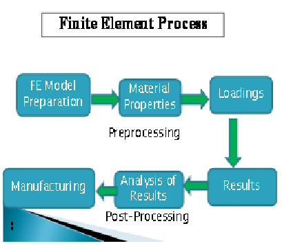
Fig. 1 Flow chart of research
First the basic sketch of the SUPD was developed by lines in the Hypermesh software.
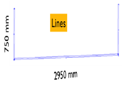
Fig. 2 Line sketch of SUPD using Hypermesh
After the sketch was generated with fixing the dimensions of lines with horizontal distance of 2950mm and vertical distance 750mm, the surface was generated.
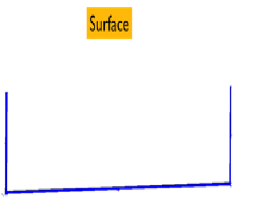
Fig.3 Surface sketch of SUPD using Hypermesh
After the generation of surface, the meshing of surface was done by Hypermesh auotmesh feature. Meshing is the discretization of the surface into finite number of nodes, and the area bounded by the nodes is called elements.
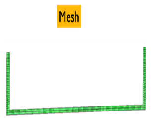
Fig.4 Meshing Of SUPD
- Material Detail
After an intensive research material for the SUPD was selected as FE: 410WA. The selection was based on the provided properties of the metal in table 1.
TABLE 1
Material properties of Fe 410WA steel
The observed data is provided to the software as material data input as shown in Fig.5
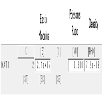
Fig. 5 Material properties input
The top edges of the SUPD are provided with SPC, single point constrains fixing the degree of points in every direction. We can term them as fixed point as it does not allow any movement in any of the direction. A load of 1 kN is being provided in the edge of the SUPD, as represented in fig 6. This whole setup represents the government testing of SUPD design for the eligibility. The thickness of the SUPD was iterated multiplel times for the optimized result.
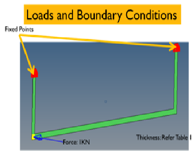
Fig.6 Load and boundary conditions
OBSERVATIONS
Thickness was iterated multiple times to obtained the lightest design passing the acceptance criteria. In order to achieve the optimized result Table 2 enlists the iterations of thickness and their corresponding weight. The main aim of the iterations is to select the best possible design.
TABLE 2
Thickness Iterations
| Iteration No. | Thickness in mm | Weight in kg |
| 1. | 10 | 20.65 |
| 2. | 9 | 18.5 |
| 3. | 8 | 16.5 |
Iteration 1
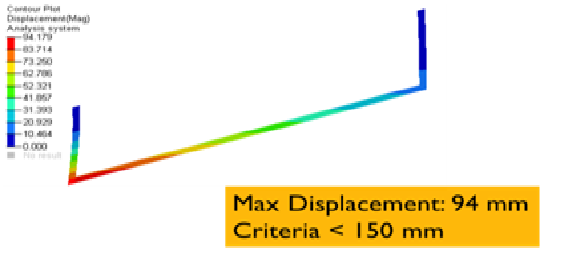
Fig.7 Iteration with thickness 10 mm
From the 1st iteration the thickness of SUPD was 10mm and it was observed that the weight of SUPD is 20.65kg. After the analysis of the iteration 1st the displacement of SUPD was found to be 94mm, as illustrated in fig. 7 This qualifies the criteria and creates a scope for 2nd iteration.
Iteration 2
.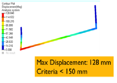
Fig. 8 Iteration with thickness 9 mm
For the 2nd iteration the thickness was further reduced by 1mm, so now the provided thickness was 9mm and the resulted weight of SUPD was 18.5kg. After the static analysis of the 2nd iterated design of SUPD, it was found that displacement increased to 128mm and nearly qualifies the criteria but still creates a hope for further iteration. Fig 8 represent the Hyperview result in form of displacement.
Iteration 3
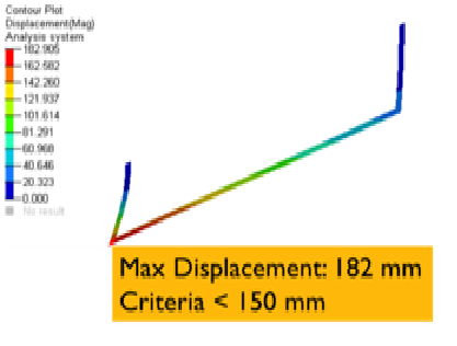
Fig. 9 Iteration with thickness 8 mm
After the 2nd iteration, the further decrement in the thickness was done by 1mm so to make the thickness of SUPD to be 8mm. The weight of the SUPD was found to be 16.kg for the 3rd iteration, but after the analysis of the 3rd iteration it was found that the displacement subsequently increased to 182mm which clearly states the failure of design according to the eligibility criteria. Fig 9 represents the result for the analysis for the 3rd iteration. No further decrement in displacement was now possible.
RESULT AND CONCLUSION
The final design of SUPD developed was a thickness of 9 mm, which resulted 18.5 kg as the weight of the design. This analysis gives us the best optimized design and safe in case if accident. Also this optimize design of SUPD will increase fuel efficiency of vehicle and save material cost to develop product. This investigation examined passenger bicycle bumping with the sides of heavy vehicles. Because of the big and unguarded gap between the road and the bottommost of the heavy vehicle can lead to under ride scenarios for the smaller vehicle like bicycle. It can often result in severe injury or death of the rider. To exclude the under ride effect, under ride guards are developed. After brief study of the norms it was possible to design the SUPD in a CAD software then testing were done according to the government test setups and the design was passed. Multiple iterations were done in the design to obtain the optimum result for the SUPD design.
REFERENCES
- V.Gadekar, M.A.Kadam, Dr.S.S.Kadam, “international journal of engineering sciences & research technology” ISSN: 2277-9655 june-2015.
- IS 14682:2004, automotive vehicle-lateral Protection (side guards) — technical Requirements.
- Mayank laddha, Dr. Neeraj kumar & avinash kumar namdeo, “International Journal of Mechanical and Production Engineering Research and Development (IJMPERD) ISSN (P): 2249-6890; ISSN (E): 2249-8001 Vol. 9, Issue 4, Aug 2019, 263-268© TJPRC Pvt. Ltd.
- Galipeau-Belair, P., El-Gindy, M., Critchley, D., Ramachandra, S., Ghantae, S. (2013). A Review of Side Underride Statistics and Protection Device Literature and Designs. Int. J. of Heavy Vehicle Systems, 20(4):361-374.
- Galipeau-Belair, P., El-Gindy, M., Critchley, D., Ramachandra, S., Ghantae, S. (2013). Development of a regulation for testing the effectiveness of a rigid side underride protection device (SUPD)”, International Journal of Crashworthiness.
- Padmanaban, J., Martz, B., Salvage, J. (2008). Evaluation of Light Vehicle Side Underride Collisions into Combination Trucks. SAE International Journal of Commercial Vehicles, 1(1): 473-480.
- Gadekar, R. V., Kadam, M. A., Kadam S. S., (2015). Flexibility of existing SUPD designs for impact load testing of motorbikes. International Journal of Engineering Sciences & Research Technology, 4(6):482-87.