Design Challenges of Battery Management System
| Kadlag Sunildatta Somnath | Mukesh Kumar Gupta |
| Research Scholar
Suresh GyanVihar University, Jaipur(Rajashtan) |
Suresh GyanVihar University, Jaipur(Rajashtan)
mkgupta72@gmail.com |
| sunilkadlag5675@gmail.com |
ABSTRACT
Every BMS work takes vitality, thus BMS architects must organize plans. Numerous BMS don’t log information, for instance, and they may miss the mark while evaluating the battery’s current state or by and large state. Be that as it may, one of the most basic capacities is securing the life of the EV’s battery. Security is indispensable in the present current vehicle. Because of the high vitality contained in the battery and the hazard in case of an impact or short out, security is a significant thought while picking a battery the executives framework. Early electric vehicles (EV), half and half electric vehicles (HEVs) and module cross breed electric vehicles (PHEVs) utilized either lead-corrosive batteries or NiMH batteries for capacity. Notwithstanding, these batteries were not ideal: EVs, HEVs, and PHEVs require noteworthy vitality stockpiling that even NiMH batteries, with a 68Wh/kg explicit vitality, aren’t able to do. Looking for higher vitality proficiency, numerous producers have gone to lithium-particle batteries, for example, lithium-titanate, lithium-phosphate and lithium-manganese, for electric vehicles. Ideal and wellbeing utilization of these batteries requires a battery the executives system(BMS). New applications, for example, vitality stockpiling frameworks (ESS) are likewise rising which could reform how vitality is made, dispersed and put away. Fashioners of these frameworks face critical difficulties of cost, plan adaptability, battery pack unwavering quality and lifetime, and wellbeing.
Keywords: Battery management system, DC to DC converter, Data acquisition, Safety protection.
- INTRODUCTION
Battery the executives frameworks (BMS) have two principle jobs: the first is to screen the battery to decide data, for example, its State of Charge, State of Health (the capacity of the battery to convey its predetermined yield) and Remaining Useful Life. These boundaries are significant for clients just as to enhance the charge and release forms and should be conveyed to on-board frameworks (security framework, correspondence with the driver, motor administration) [3]. Distinctive demonstrating strategies have been proposed in the writing [4]. The subsequent job is to work the battery in a sheltered, proficient and nondamaging way. As can be seen Fig. 3, battery squares are made out of cells organized in equal and arrangement to address the issues of the motor [5]. As those cell qualities can vary somewhat, it is important to adjust the charge between every cell to forestall harm and improve the lifetime of the stack. Inactive adjusting techniques have been utilized, during charge, utilizing dispersal through resistors, however it’s anything but a proficient arrangement. Second era batteries will most likely depend on dynamic cell adjusting, one technique being introduced in [8, 9]. It includes voltage and current observing in every phone, and temperature checking in numerous focuses to guarantee that none of the cell is working outside its operational conditions. The advantages offered are a more drawn out schedule and cycle life, expanded wellbeing and a more powerful ability for a moderately little cost increment. It is especially significant for Lithium-particle advances since, notwithstanding their guarantees, they can be harmed and present a danger of fire or blast on the off chance that they are overseen inaccurately, and their significant expense makes much increasingly urgent an expansion in their cycle and schedule lives. So as to meet these objectives, scientific models of the conduct of every battery innovation have been expounded [10]. It has been proposed models that consider the adjustment in limit and impedance of batteries during their lifetime (diminishing the accessible force), the model taking into account the observing and expectation of corruption, and the improvement of cutting edge charging calculations to boost the battery life [11]. These, nonetheless, require from cell makers a significant level of consistency in their items. It is accepted that best in class BMS can essentially improve the proficiency of BEVs and expand the life of batteries. As these two boundaries are urgent for both range and life cycle cost of BEVs, enhancements in this innovation could relieve the current social acknowledgment troubles.
- BATTERY PACK DESIGN CHALLENGES
At the beginning of the battery pack design the needed battery size as well as the cell type and chemistry have to be chosen. Those factors are directly influenced by the usage scenario of the battery. The usage scenario and its estimated load profile enable to calculate the needed energy consumption during one day of operation or in between two charging stops. Therefore, the battery size can be dimensioned large enough with a sufficient reserve. Doing so it has to be kept in mind to calculate with batteries at their end of life as the capacity fade and the growing internal resistance have to be considered. Tough, especially in fleet applications and public transport it might not be possible to fulfill the daily driving range without recharging as this would lead to expensive and too heavy batteries with an enormous required space. Therefore, profound concepts with intermediate fast charging stops and a stepwise declining state of charge (SOC) have to be considered in these cases. A BMS need to be linked with all battery components, as well as with the vehicle’s computer. The BMS will take several sensor readings:
- Detecting the cells’ voltage and timing the battery’s charging or releasing.
- Sensing and controlling temperature. Abnormally high or low cell temperatures demonstrate difficult issues in progress.
- Detecting current. Irregular current demonstrates a danger and gives information to calculations that decide the battery’s current state and generally speaking wellbeing.
- Sensing and reacting to ground faults.
- Taking logs on unusual readings for real-timeand later diagnostics.
- Communication with other battery components.
- Prolonging battery life
Taking the numerous sensor readings recorded above represents a plan challenge, with respect to the physical structure of the battery. Arrangement and equal associated cell structures both make precise observing. Organizations have customarily utilized unified, disseminated and particular capacities to address the issues of BMS frameworks. While numerous compact gadgets have modern BMS frameworks, EV, HEV, and PHEV BMS have generally falled behind these because of the muddled assignment of adjusting the many powerful cells in an EV’s battery. Cell adjusting frequently includes the improvement of new calculations and progressively exact identification strategies, albeit gradual structure changes have helped with cell adjusting also. Disengagement is likewise basic, to shield fragile frameworks from batteries’ high vitality. That is the reason Pulse Electronics has planned seclusion transformers and basic mode gags for battery the board frameworks. These separate different high-vitality cells from each other, to improve security and generally work.
The least difficult topology that takes into account singular cell observing is a solitary series of arrangement associated battery cells.
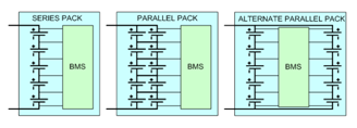
Figure 1. Main topologies for cells in battery pack
An increasingly confounded topology is essential when the limit of a battery pack needs to increment yet the general voltage needs to continue as before. This requires a parallel association of battery cells.
If the parallel connection occurs at the per-cell level, an approximation is made that each cell in the parallel string contributes equally to the overall health of the parallel string. This approximation has the undesirable consequence of reducing the accuracy of the BMS. A parallel connection at the total pack voltage is better, as it allows the BMS to read the state of each individual cell.
Similarly as there are various cell topologies, there are likewise different systems for cell adjusting. Cell adjusting brings every phone into arrangement and guarantees that every phone inside the battery pack has equivalent condition of charge (SoC).
- THERMAL MANAGEMENT
The general aim of a thermal management system is to keep the battery within a relatively narrow temperature range. Deep temperatures have to be avoided as they go along with a lower power capability and as charging below zero degrees Celsius might result in lithium plating and is therefore not applicable for most lithium-ion battery technologies. High temperature then again reduces lifetime tremendously and the maximum charge current is limited by the cell temperature. A potential overheating of the cells might lead to a thermal runaway and therefore rises the safety issues of lithium-ion battery packs. A thermal runaway is an uncontrolled increase in temperature. In lithium-ion batteries it can be triggered by an internal short circuit, physical damage or overheating. The initial event triggers an exothermal process that produces heat and goes along with the decomposition of the electrolyte which boosts the exothermal process once more and leads to a self-energizing uncontrolled temperature rise. The result of a thermal runaway in a lithium-ion battery is severe and ultimately leads to a fire or explosion. Over temperatures therefore have to be avoided by all means and an accurate temperature measurement is necessary.
- CIRCUIT PROTECTION CHALLENGES
The market for higher-voltage car frameworks is extending. The quantity of electric vehicles that utilization battery-fueled drive frameworks having voltage equivalent to or higher than 48V is required to develop by twofold digits in the coming years. As the two shoppers and governments press toward less dependence on petroleum products and request improved air quality through lower or zero discharges, electric vehicles are moving to the bleeding edge. Simultaneously, electric frameworks contain a more noteworthy level of generally speaking car work. Parts that used to be driven precisely or using pressurized water presently require higher voltage and all the more remarkable batteries. Locally available amusement, security, and comfort highlights add to the electric draw. Lithium-ion batteries have risen as the innovation answer for electric vehicles. The points of interest incorporate force thickness and charging cycle life; in any case, to work securely, lithium-ion batteries need consideration in observing and assurance. Dependable battery action is just conceivable with a condition of charge kept up between 20% to 90%. Unnecessary current stream may causes shorts and dendritic lithium plating, which decimates the cell. Under-voltage may be reason for shorts and breakdown in terminal materials. Over the top temperature can trigger a chain response of occasions, from shorts to outgassing of combustible gases from natural solvents. For every one of these reasons, originators utilize battery the board frameworks that forestall expensive and conceivably perilous battery disappointments.
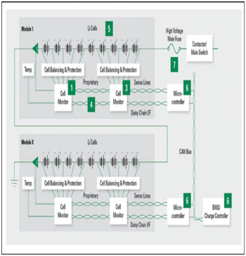
Fig.1. A BMS system need protection from threats such as overcurrents, surges, and ESD. Points for circuit protection include fuses (1), TVS diodes (3, 5), TVS diode arrays (4, 6), and high-voltage fuse (7).
Fashioners and suppliers agree that circuit security is mission-essential in electric vehicles using a high-essentialness structure working at numerous volts and amps. Because of a setback, a hurt, collapsed, or punctured battery can incite a warm scene or contact with the metal body of the vehicle. Setup engineers attempt to discard the opportunity of such events, and to do so requires acknowledging which wires to use and where to put them. Affirmation goes past execution and to the prosperity of the buyer, similarly as the association’s image and reputation. The breakers used in these applications must meet remarkable execution measures. Wires should have a low-temperature derating. As opposed to “flexible” batteries in PDAs or tablets, these breakers must change in accordance with temperature cycles and vibrations. The little structure factor is crucial. The structure needs to combine a lifecycle of 15 years, more than 150,000 miles of road vibrations, and 8,000 hours of movement. The battery board framework keeps up the sheltered activity of the high-voltage battery, and can hand-off data about the battery to power and vitality the board frameworks. The battery the board framework requires assurance from dangers, for example, overcurrents, floods, and electrostatic release (ESD). Breakers, TVS diodes, and diode clusters guard this framework dependable and under all conditions, from the get together to upkeep and ordinary activities. The battery the board framework’s voltage range and intrude on rating prerequisites rely upon the battery design. Inside the framework, every module of batteries has cell observing frameworks. These subsystems screen the voltage for legitimate parity. Microcontrollers at that point administer every one of these modules to give the most noteworthy vitality productivity and longest existence of a battery.
V. VEHICLE CHARGING SYSTEM
Vehicle purchasers see the working separation go per charge as a disadvantage in half and half and electric vehicle reception. A fast battery charge framework lightens this protest, yet requests the vehicle producer improve locally available charging and force thickness in the limited space accessible. Force electronic converter misfortunes challenge electric vehicles. The decrease in size of inductors and transformers with silicon semiconductors would bring down framework size, weight, and cost, and increment working separation run. Tragically, silicon (Si) semiconductors demonstrate illogical in scaling down on the grounds that the semiconductors in a similar circuit must be controlled at a high exchanging recurrence. High intersection temperatures and warm burden at high exchanging recurrence are unrealistic at an on-off change pace of 50 to 100 ns. Conversely, silicon carbide (SiC) MOSFETs can work productively with higher warm loads, exchanging up to five to multiple times quicker than silicon MOSFETs, at 10 ns. When hard to produce, SiC MOSFETs are moving standard. Their productivity makes them appropriate for high-voltage and high-power electric vehicle applications. SiC MOSFETs utilized in the plan of inverters and other force converters diminish size and weight of different parts, without loss of intensity thickness. Their roughness. unwavering quality, and sensible expense demonstrate beneficial to environmentally friendly power vitality producing interests.
- BMS SCOPE AND FAILURE CONSEQUENCES
The diagram below indicates the possible cell failure mechanisms, their consequences and the necessary actions to be taken by the Battery Management System
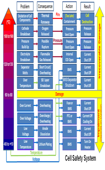
Fig.2. Cell Failures, Consequences and Protection Mechanism
The BMS has to protect the battery and the user under all of these conditions
VII. CONCLUSION
For the makers of a high-voltage battery the board framework, there are principal building hinders in the plan. The cells are associated in arrangement, making up a module. As modules interface in arrangement, the complete voltage of the framework increments. The arrangement of modules in amount and associated in equal expands the voltage of the battery and the vitality limit. As cells and modules are added to a battery the executives framework, the unpredictability and cost increments. The test is to locate the right equalization of cells/modules, unpredictability, and cost to make a sheltered and productive framework. The originator’s chosen design for the battery the executives framework decides the assurance boundaries. High-voltage wires are utilized to decrease the danger of a short out under high-voltage conditions, both in the module and between the cells in a mishap. Two kinds of disappointment must be considered: short circuits and over-burden conditions. The battery pack is to maintain within a relatively narrow temperature range
REFERENCES
[1] ArashShafiei , Sheldon S. Williamson “Plug-in Hybrid Electric Vehicle Charging: Current Issues and Future Challenges”2010 IEEE Vehicle Power and Propulsion Conference Year: 2010, IEEE Conferences
[2] L. Tang , G. Rizzoni “ Battery Life Extending Charging Strategy for Plug-in Hybrid Electric Vehicles and Battery Electric Vehicles” 8th IFAC Symposium on Advances in Automotive Control AAC 2016 Norrköping, Sweden, 20—23 June 2016 Volume 49, Issue 11, ELSEVIER
[3] Mohsen Ahmadi ; N. Mithulananthan ; Rahul Sharma “A review on topologies for fast charging Vehicles for Electric Vehicles“2016 IEEE International Conference on Power System Technology (POWERCON), Year: 2016, IEEE Conferences
[4] Jung-Hyo Lee ; Jung-Song Moon ; Yong-Seok Lee ; Young-Real Kim ; Chung-Yuen Won “Fast Charging Technique for EV Battery Charger using three-phase AC-DC Boost Converter” IECON 2011 – 37th Annual Conference of the IEEE Industrial Electronics Society, Year: 2011, IEEE Conferences
[5] Quirinkellner ,ElhamHosseimzadeh , Gael Chouchelamane, WidanalageDhammikaWidanage, James Marco “Battery cycle life test development for high-performance electric vehicle applications” Journal of energy storage (2018) ELSEVIER
[6] M. Kokila, P. Manimekalai& V. Indragandhi “Design and Development of battery management system(BMS ) using hybrid multilevel convertor” in International Journal of Ambient Energy · June 2018, Taylor &francis
[7] [60] DevangKirtikumarBhatt , Mohamed El. Darieby “An Assessment of Batteries form Battery Electric Vehicle Perspectives”2018 IEEE International Conference on Smart Energy Grid Engineering (SEGE), Year: 2018, IEEE Conferences
[8] Lin Fu, Chenghua Zhu & Tao Du “A new type battery management system for Li-ion cell pack” Journal of Interdisciplinary Mathematics Vol. 20 (2017),taylor& Francis
[9] Yong Feng, Zhenwei Cao ,Weixiang Shen ,Xinghuo Yu ,Fengling Han ,Rita Chen ,Jiangfeng Wu “Intelligent Battery Management for Electric & Hybrid Electric Vehicles: A Survey” 2016 IEEE International Conference on Industrial Technology (ICIT)
[10] Li Haiying ; Jia Yongli ; Zhang Dan ; Qiu xinghong “Application of Electrical Vehicles battery intelligent Monitoring & Management System” 2014 IEEE Conference and Expo Transportation Electrification Asia-Pacific (ITEC Asia-Pacific)
[11] Philip Dost ; Constantinos Sourkounis “Battery Management System Realisation for Electric Vehicles”22nd Mediterranean Conference on Control and Automation, Year: 2014, IEEE Conferences
[12] Wen-Yeau Chang “The state of charge Estimating Methods for Battery: A Review” Hindawi Publishing Corporation ISRN Applied Mathematics Volume 2013, Article ID 953792,
[13] M. Brandl , H. Gall , M. Wenger ,V. Lorentz ,M. Giegerich , F. Baronti ,G. Fantechi , L. Fanucci ; R. Ro “Batteries and Battery Management system for Electric vehicles” 2012 Design, Automation & Test in Europe Conference & Exhibition (DATE). Dresden, Germany, IEEE
[14] M. Maskey ; M. Parten ; D. Vines ; T. Maxwell “An Intelligent battery management system for electric and hybrid electric vehicles” 1999 IEEE 49th Vehicular Technology Conference (Cat. No.99CH36363), Year: 1999 , Volume: 2, IEEE Conferences
[15] Feng Nenglian ,Yong Jiawang , Bin Yang , Peng Jiankun , Tang Yanrong “Research on battery management system for light electric vehicle” Proceedings 2011 International Conference on Transportation, Mechanical, and Electrical Engineering (TMEE) Year: 2011, IEEE Conferences
[16] B.P. Divakar , K.W.E. Cheng , H.J. Wu , J. Xu ; H.B. Ma , W. Ting , K. Ding , W.F. Choi , B.F. Huang ; C.H. Leung “Battery management system and control strategy for Hybrid and Electric Vehicle” 2009 3rd International Conference on Power Electronics Systems and Applications (PESA). Year: 2009, IEEE Conferences
AUTHORS PROFILE
 |
Mr. Sunildatta Somnath Kadlag did B.E in Electrical Engineering from Dr. B.A.M.U. Aurangabad in 1997 and M.E in Electrical Engineering (Contol System) from College of Engineering Pune (Pune University) in 2005. He is Currently pursuing Ph.D in Electrical Engineering from Suresh Gyan Vihar University Jaipur (Rajasthan). His research field area is Electric Vehicle. |
 |
Dr. Mukesh kumar Gupta did B.E in EIC from Rajasthan university Jaipur in 1995 and M.E in Electrical Engineering (Power System) from Rajasthan university in 2009. He had done Ph.D. in Electrical Engineering from Jagannath University Jaipur in 2014. His research area is Renewable energy. He is presently working as Professor and Associate Dean Research at Suresh Gyan Vihar University Jaipur (Rajasthan). |