pp.37-44
Mohammed Ali1* Sachin T. Gadakh2 and S.K. Somani3
1PhD Research Scholar, Suresh Gyan Vihar University, Jaipur 302025, India e-mail:
2Asst. Professor, Department of Mechanical Engineering, AVCOE, Sangamner, India.
3Department of Mechanical Engineering, Medi-Caps Institute of Technology and Management,Indore 453331, India
*Corresponding Author email: hasnaat 2005@yahoo.co.in.
ABSTRACT
This paper deals with the bearing design based on heat balance i.e. heat generated inside the bearing should be nearly equal to the heat dissipated from the bearing housing to the surrounding. This analysis is based on computer aided bearing design process. As it is an iterative process of bearing design, the use of computer provides more accurate, optimum, easy and fast calculations. This paper also gives the software tool for finding the effect of various parameters such as oil grade, lubrication system, bearing housing geometry, R/C and L/D on the operating temperature of the hydrodynamic journal bearing.
Key words: bearing design, heat balance, operating temperature.
Introduction
Hydrodynamic journal bearing is used in many industrial applications. As it plays a very significant role in many applications, its design needs much accuracy. The conventional method includes the use of various charts and tables in journal bearing design. But this is time consuming and not so much appropriate method of design. That’s why a CAD tool is needed to develop for a fast and accurate design of journal bearing. Two types of parameters are used in design of journal bearing viz. operating parameters and performance parameters. Operating parameters are under the control of the designer, but performance parameters are not directly under control the designer. Performance parameter shows how well the bearing is performing. Certain limitations on their values are imposed according to the designer guidelines, to assure satisfactory performance.
The operating temperature is one of the significant performance parameters which is needed to be found out for safe operation of the bearing. To measure the operating temperature of fluid film bearing, Glavatskih S. B. et al. [4] in 2001 gave eddy current sensor technique. The test was conducted for various operating conditions like rotational speed, bearing load and oil flow rate to check the performance of sensor used. The results show that the sensor can effectively monitor the condition of bearing as compared with the thermocouple installed in the pads and collar. Further, Glavatskih S. B. et al. [3] in 2004 developed a new method for monitoring a temperature in fluid film bearing. In this method the lubricating oil comes in direct contact with thermocouple through a special arrangement. The temperature obtained is compared with those measured by thermocouple in the pad backing and in the collar. This method provides high sensitivity for temperature monitoring.
Compact designed journal bearing needs severe operating condition to work. Hence, Wang Yansong et al. [10] gave a steady state mixed TEHD (Thermo Elasto Hydrodynamic) model. The model is compared with the experimentally obtained results and change in temperature has been studied numerically and experimentally.
Sharma S.C. et al. [7] studied the performance of a hole-entry hybrid journal bearing system by considering variation of viscosity corresponding to the temperature rise of the lubricant. The thermo elastohydrostatic performance of a given bearing has been studied for a particular operating and geometric parameters. It has been observed that the static and dynamic performance of a hole-entry hybrid journal bearing system gets affected by the variation of viscosity due to temperature rise of lubricant. Singh U. et al. [9] in 2008 studied theoretically the thermo hydrodynamic analysis of an axial groove journal bearing. Simultaneous solution of Reynolds equation, energy equation and heat conduction equation is used for this analysis. The results show that the temperature of the fluid film increases due to frictional heat. Due to numerical instability, this method cannot be adopted for high eccentricity ratios. Roy L. [6] in 2009 studied the thermo hydrodynamic performance of grooved oil journal bearing for different feeding position and it is observed that 12o feeding groove locations is good over other feeding location.
Garg H.C. et al. [2] in 2010 studied thermal and rheological effects of lubricants on the performance of symmetric and asymmetric slot-entry hybrid journal bearing system. The result obtained shows that the bearing performance is affected by the variation of viscosity due to temperature and non Newtonian behaviour of lubricant.
Boubendir S. et al. [1] in 2011 numerically studied the thermo-hydrodynamic performance of journal bearing and found that temperature affects on the performance of journal bearing. This paper includes the design of bearing for stable zone by considering the bearing characteristic, 0.362 x 10⁻⁶ [8] and finding the operating temperature for heat generation to be equal to heat dissipation for certain value of R/C ratio, L/D ratio and SAE grade oil.
Bearing Design Procedure
As for stable bearing operation the bearing temperature should not reach in severe temperature zone, there should be thermal balance in bearing operation i.e. the heat generated inside the bearing should get dissipated to the surrounding. Now, to design the bearing for a particular load and journal speed, let us assume initially some values for the parameters like L/D ratio and R/C ratio, also assume some SAE oil grade. Before starting the bearing design, select the value of overall heat transfer coefficient (U) which depends upon the bearing material, geometry of the bearing, roughness, the temperature difference between housing and the surrounding objects and air velocity. Also, select the Karelitz’s constant () according to lubrication scheme and the bearing housing geometry.
|
TABLE-I: OVERALL COEFFICIENT FOR DIFFERENT CONDITIONS [8]
33.4 For air moving at 2.5 m/s
TABLE-II: KARELITZ’S CONSTANT () FOR DIFFERENT LUBRICATION SCHEME AND CONDITIONS[8]
| Lubrication System | Conditions | Range of |
| Oil ring | Moving air | 1-2 |
| Still air | ½ -1 | |
| Oil bath | Moving air | ½ -1 |
| Still air | 1/5 – ½ |
Step 1: Initially assume some operating temperature of the bearing. Now, for this operating temperature and assumed SAE grade oil, the viscosity can be found out by using the chart given in reference [8] or using the formula,
0 exp [b / (1.8 T + 127)] …(1)
The values for 0 and b for different SAE grade oil can be obtained from the Table-3.
TABLE-III: VALUES OF 0 AND B FOR DIFFERENT SAE GRADE OIL[8]
| SAE Oil
grade |
Viscosity 0, mPas | Constant b, oC |
| 10 | 0.1089 | 1157.5 |
| 20 | 0.0937 | 1271.6 |
| 30 | 0.0971 | 1360.0 |
| 40 | 0.0827 | 1474.4 |
| 50 | 0.1171 | 1509.6 |
| 60 | 0.1288 | 1564.0 |
Step 2: To calculate the value of length of bearing and corrected pressure,
For thick film lubrication inside the bearing, the bearing characteristic should be greater than or equal to 0.362 x 10⁻⁶.
0.362 x 10⁻⁶ …(2)
From this, the overall pressure inside the fluid film can be calculated as,
P = …(3)
This pressure can also be defined as the load per unit projected area,
P = …(4)
By comparing equation (3) and equation (4), the length and diameter of the bearing can be obtained. These obtained values of length and diameter may be in fraction so round up it into immediately next integer value and for these corrected values find out the corrected pressure.
Step 3: Now, calculate the value of Sommerfeld number as,
S = …(5)
From Raimondi and Boyd [5] chart for coefficient of friction variable Vs Sommerfeld number, find the value of coefficient of friction variable for an assumed L/D ratio. As we have assumed the R/C ratio initially, the coefficient of friction can be calculated from this.
Step 4: Finding the heat generation inside the bearing.
When journal rotates inside the bearing, the shearing action takes place between the layers of lubricant, which causes the heat generation. Heat generation can be found out mathematically,
= f x WD x N …(6)
Step 5: Heat dissipation from the bearing housing.
Heat dissipation is the phenomena in which heat dissipates from the bearing housing to the surrounding and the amount of heat dissipated can be found out mathematically as,
= …(7)
If , then the design of bearing is stable and if it is not so, then iterate the procedure by changing the operating temperature till the required condition is obtained. In this paper the computer aided design procedure is adopted which helps to iterate the process for small step of temperature variation. Also the computer aided design process allows us to vary the assumed L/D ratio, R/C ratio and SAE Oil grade.
Use of Software Tool and Obtained Graphical Results
According to the above mentioned mathematical procedure of bearing design, a software tool can be prepared by using Matlab software. The GUI of that tool is shown in the fig.1. This GUI helps us to give input of different values such as Load, RPM, L/D, R/C, SAE grade of oil, overall heat transfer coefficient and value of alpha. According to this input values,
software tool calculate the values of operating temperature, minimum film thickness and coefficient of friction. By making the use of speed of this software tool, one can try many possible values for the design and optimization of the hydrodynamic bearing. Also, by using this tool, we can plot the graphs as shown in Fig.2 to Fig.19 which can help directly like a graphical database. Basically, the bearing designed for particular condition of load and speed of shaft. Let us assume, the bearing is to work at load of 2500N and speed of 900RPM. Now, the required operating temperature for any particular L/D ratio can be observed from the graphs shown in Fig.2 to Fig.19.
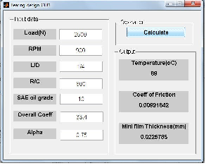
Figure-1: GUI of software tool
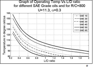
Figure-2: Graph of Operating Temp Vs L/D ratio for U=11.3, =0.3 and R/C=800
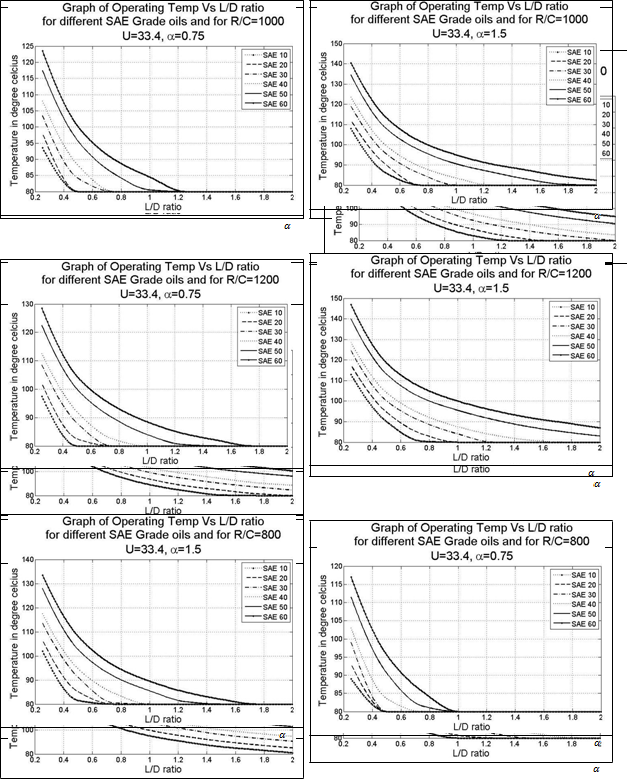
Figure-3: Graph of Operating Temp Vs L/D ratio for U=11.3, =0.3 and R/C=1000
Figure-6: Graph of Operating Temp Vs L/D ratio for U=11.3, =0.75 and R/C=1000
Figure-4: Graph of Operating Temp Vs L/D ratio for U=11.3, =0.3 and R/C=1200
Figure-7: Graph of Operating Temp Vs L/D ratio for U=11.3, =0.75 and R/C=1200
Figure-5: Graph of Operating Temp Vs L/D ratio for U=11.3, =0.75 and R/C=800
Figure-8: Graph of Operating Temp Vs L/D ratio for U=15.3, =0.75 and R/C=800
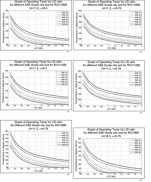
Figure-9: Graph of Operating Temp Vs L/D ratio for U=15.3, =0.75 and R/C=1000
Figure-10: Graph of Operating Temp Vs L/D ratio for U=15.3, =0.75 and R/C=1200
Figure-13: Graph of Operating Temp Vs L/D ratio for U=15.3, =1.5 and R/C=1200
Figure-11: Graph of Operating Temp Vs L/D ratio for U=15.3, =1.5 and R/C=800
Figure-14: Graph of Operating Temp Vs L/D ratio for U=33.4, =0.75 and R/C=800
Figure-12: Graph of Operating Temp Vs L/D ratio for U=15.3, =1.5 and R/C=1000
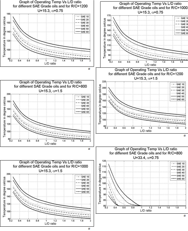
Figure-15: Graph of Operating Temp Vs L/D ratio for U=33.4, =0.75 and R/C=1000
Figure-16: Graph of Operating Temp Vs L/D ratio for U=33.4, =0.75 and R/C=1200
Figure-17: Graph of Operating Temp Vs L/D ratio for U=33.4, =1.5 and R/C=800
Figure-18: Graph of Operating Temp Vs L/D ratio for U=33.4, =1.5 and R/C=1000
Figure-19: Graph of Operating Temp Vs L/D ratio for U=33.4, =and R/C=1200
From these figures, for a particular value of L/D ratio and operating temperature, one can get sets of SAE oil grade, R/C, U and α value. One of such sets is shown in Table-IV. From such set of values, one can choose optimum set according to the SAE oil grade available, provision of mode of heat transfer, lubrication scheme and bearing housing geometry. In another way, one can make a set of differ L/D values, SAE oil grade, U and α for particular value of operating temperature and R/C value as shown in Table-5, Table-VI and Table-VII. Same type of tables can be made for different values of operating temperature, L/D, R/C, SAE oil grade, U and α.
TABLE-IV: VALUES OF SAE OIL GRADE, U AND Α FOR
PARTICULAR VALUE OF OPERATING TEMPERATURE AND
L/D
| Toperating (oC) | L/D | SAE oil
grade |
R/C | U
W/ (m2 oC) |
Α |
| 100 | 1 | 10 | 1200 | 11.3 | 0.75 |
| 30 | 800 | 15.3 | 1.5 | ||
| 20 | 1000 | 15.3 | 1.5 | ||
| 10 | 1200 | 15.3 | 1.5 | ||
| 60 | 1200 | 33.4 | 1.5 |
Results and Discussion
|
TABLE-V: VALUES OF L/D, SAE OIL GRADE, U AND Α FOR R/C=800 AND ANY PARTICULAR VALUE OF OPERATING TEMPERATURE
|
TABLE-VI: VALUES OF L/D, SAE OIL GRADE, U AND Α FOR R/C=1000 AND ANY PARTICULAR VALUE OF OPERATING TEMPERATURE
|
TABLE-VII: VALUES OF L/D, SAE OIL GRADE, U AND Α FOR R/C=1200 AND ANY PARTICULAR VALUE OF OPERATING TEMPERATURE
In inverse direction also one can use these graphical results i.e. for given condition of L/D, R/C, SAE oil grade, U and α, one can decide the operating temperature generated. Such a developed graphical database for different load and speed conditions can be used directly while designing the bearing.
The user friendly GUI of bearing design as shown in fig.1 helps designer to try many possible combinations of different design parameters and hence accordingly can select the optimum design for the bearing. The different operating temperatures are achieved according to the different L/D and R/C ratio selected. Also it varies according to the lubricating oil, lubrication scheme and air velocity. The graphs for operating temperature versus L/D ratio have been plotted for different SAE oil grade considering various values of U and as shown in Fig.2 to Fig.19. It has been observed from all these graphs that as the value of L/D ratio increases, the operating temperature achieved decreases gradually. Also, the operating temperature of the oil increases according to the increase in SAE grade of an oil. It is observed from Fig.2 to Fig.19 that for different SAE oil grade, the value of operating temperature increases as the value of R/C increases for any particular value of U and . It has also found that for any particular value of R/C and U, as the value of increases, the value of operating temperature increases. The value of operating temperature decreases for all SAE oil grade, as the value of U increases for any fixed value of R/C and . In the same way one can plot the graphical results for the minimum film thickness and coefficient of friction.
Conclusion
The conclusions of this study are,
This CAD application provides more precise results as it allows to take more fine guess step of the operating temperatu
This CAD application gives fast bearing design without any manual error in calculation.
Many possibilities of bearing design can be tried and compared to get the optimum design.
The reference data base can be prepared which helps to decide the value of L/D ratio, R/C ratio, SAE grade oil, U and for a desired value of operating temperatu
As L/D ratio increases, the operating temperature decreases gradually.
For higher grade oil, the operating temperature range is also higher.
As lubrication scheme improves, the operating temperature range decreas
-
APPENDIX NOMENCLATURE b Constant R radius of journal (m)
C radial clearance (m)
S Sommerfeld number
D diameter of the bearing (m)
Operating temperature (0C)
E eccentricity (m) Atmospheric temperature (0C)
F Coefficient of friction
U combined overall coefficient of radiation and convection heat transfer (m2 0C)
H lubricant film thickness (m)
Load (N) Heat generation Karelitzs constant Heat dissipation Eccentricity ratio = e/C
L length of bearing (m)
Slenderness ratio (L/D)
N journal rotation speed (rpm)
Journal angular speed (rad/s)
P film pressure (Pa) µ Viscosity of lubricant film (Pa s)
- The operating temperature varies in proportional to the air flow velocity over the bearing.As R/C ratio increases, the operating temperature also increas
References
[1] Boubendir S., Larbi S., Bennacer R., “Numerical Study of the Thermo-hydrodynamic Lubrication Phenomena in Porous Journal Bearings”, Tribology International 44 (2011) 1–8.
[2] Garg H.C.,Vijay Kumar, Sharda H. B., “Performance ofSlot-entry Hybrid Journal Bearings Considering Combined Influences of Thermal Effects and Non-Newtonian Behavior of Lubricant”, Tribology International 43 (2010) 1518–1531. [3] Glavatskih S. B., “A Method of Temperature Monitoring in Fluid Film Bearings”, Tribology International 37 (2004) 143–148.
[4] Glavatskih S. B., Uusitalo O., Spohn D. J., “Simultaneous Monitoring of Oil Film Thickness and Temperature in Fluid Film Bearings”, Tribology International 34 (2001) 853–857. [5] Raimondi A, Boyd J. “A Solution for the Finite Journal Bearing and its Application to Analysis and Design – Part III”. Trans. ASLE, vol. 1, No 1, April, 1958; pp. 194-203.
[6] Roy L., “Thermo-hydrodynamic Performance of Grooved Oil Journal Bearing”, Tribology International 42 (2009)118-119
[7] Sharma S. C., Vijay Kumar , Jain S.C., Nagaraju T. , “Study of Hole-entry Hybrid Journal Bearing System Considering Combined Influence of Thermal and Elastic Effects”, Tribology International 36 (2003) 903–920.
[8] Shigley J. E. and Mischke C. R., “Mechanical Engineering Design(in SI units)”, sixth edition, Tata McGraw Hill publishing; 2003.
[9] Singh U., Roy L., Sahu M., “Steady-state Thermo-hydrodynamic Analysis of Cylindrical Fluid Film Journal Bearing with an Axial Groove”, Tribology International 41(2008) 1135–1144.
[10] Wang Y., Zhang C., Wang Q. J., Lin C., “A Mixed- TEHD Analysis and Experiment of Journal Bearings Under Severe Operating Conditions”, Tribology International 35 (2002) 395–407.